Diagram 3 Way Valve In Chilled Water System

Learn More About Hvac Three Way Valves Industrial Controls

Pin On Bs

3 Way Ball Valves Home Brew Forums Homebrewtalk Valve Home Brewing

Variable Flow In Hydronic Systems With Three Way Control Valves

Valve Symbols Used In Boiler Hvac Plumbing Industrial And Other Process Applications Tubulacoes Industriais Engenharia Mecanica Engenharia Quimica
Chilled Water Pump Design Guide How To Size And Select A Chilled Water Pump

Both 3 way and 2 way valves can serve many purposes.
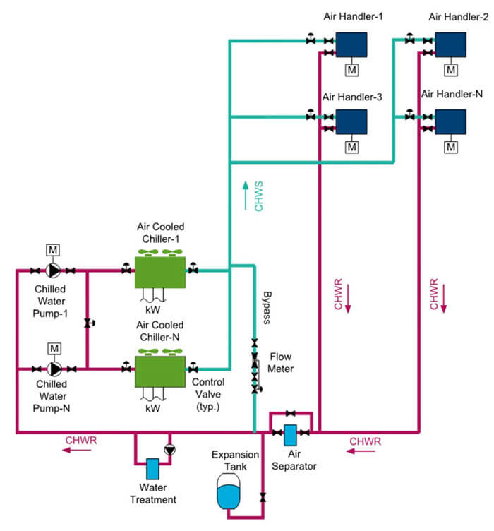
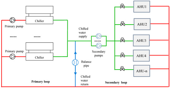
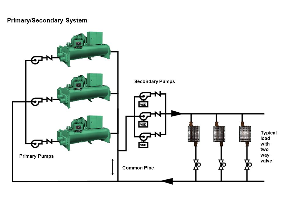
Diagram 3 way valve in chilled water system. Variable primary chilled water pumping system with some 3 way valves single chiller single variable speed pump 3 way valves for some chilled water coils to maintain minimum flow required for chiller. As the temperature from the terminal unit or coil is satisfied the flow rate is reduced in the coil and the flow is diverted to the bypass. This is a low d p application. Chilled water schematics in this video we look at how to read a chilled water schematic for central plant chilled water system covering chillers cooling to.
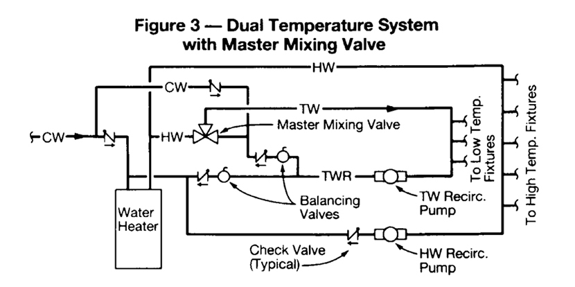
Chilled water schematic and condenser water schematic how to read and understand the engineering drawings with real world examples illustrations animations and video tutorial. In the heating mode the return line from the room terminal units typically fan coils or unit ventilators bypasses the chiller and goes to a header that feeds the boilers. As in two way valves if the three way valve selected is less than line size don t forget the fp factor. A schematic of a generic system is shown in figure 2.
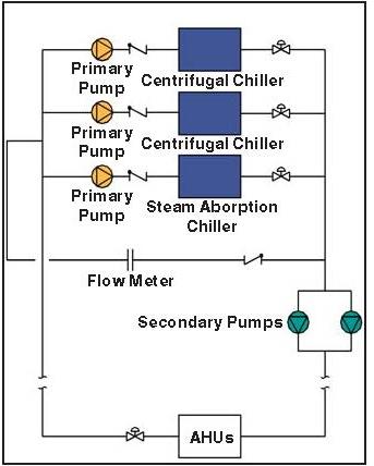
Fcu ahu applications of 2 way and 3 way valves. A chilled water system is a cooling system in which chilled water is circulated throughout. System flow below chiller min flow 250 gpm variable primary flow at 25 system load two way valves control capacity by varying flow of water in coils per chiller system load 50 tons 176kw 50tons 176 kw primary bypass flow 250 gpm 95 l s 150 gpm 9 5 l s delta t 12 of 6 7 oc 100 gpm 44 ºf 6 3 l s 6 7 ºc 56 ºf 13 3 ºc 150. Resize the valve applying the fp factor to find the new cv.
The three way valve immediately above the chiller at the bottom of the diagram switches the system s mode of operation. The sketch below shows a three way diverting valve system. They are both employed in chilled water systems as previously mentioned. Chillers have minimum flows that are typically higher than their associated vfds and pumps.
The 3 way valves restrict water supply to the cooling coil allowing some chilled water 44 f to bypass directly into the return line water stream temperature of 56 f. The decision over whether to use a 2 way or 3 way valve is made at the design stage based on application specific design and cost considerations. Covering chillers pump sets ahus risers primary and secondary systems cooling towers and bypass lines. Three way control valves may be diverting or mixing depending on how they are ported and controlled.
Https Www Engproguides Com Expansion Tank Chilled Water Design Guide Pdf

Refrigeration Cycle Hvac Maintenance Refrigeration And Air Conditioning Power Engineering

Water Tank Installation Water Storage Tanks Water Storage Domestic Water Pumps

Control Valve Split Range Example In 2020 Petroleum Engineering Control Valves Valve

Hvac Engineer Salary Hvac Work Van Bending Hvac 7 8 Tubing Videos Hvac Tools Kit Set For In 2020 Refrigeration And Air Conditioning Hvac Air Hvac Maintenance

Chilled Water System Basics Hvac Commercial Cooling

Pin On Hvac

Lamminpainevesi Jarjestelma Heating Systems Water Heating Diagram

Water System Control Valve Fundamentals Industrial Controls
Image Result For Anatomy Of Hot Water Tank Hot Water Heater Repair Gas Water Heater Water Heater

Pin By Tamas Fodor On Engineering Process Engineering Process Control Industrial Engineering

Valve Symbols Blueprint Reading Plumbing Construction Symbols

Automated Brewery Valve Layout Diagrams Home Brew Forums Beer Brewing System Beer Brewing Equipment Home Brewing

Needle Valve Small Port And Threaded Plunger That Allows For Precise Flow Low Flow Rates Building Systems Floor Plans Plunger
Burn Basics 2018 03 20 Phcppros

Boiler Flow Diagram Google Search Boiler Water Supply Cold Water

Tired Of Waiting For Hot Water And Wasting Cold Water Hot Water Recirculation Loops Charles Buell Inspections Inc Diy Plumbing Plumbing Pex Plumbing

كيف تتم عملية توزيع الهواء البارد لشيلير في الغرفة Cold Air Distribution Hvac System Hvac Cooling Tower
Https Encrypted Tbn0 Gstatic Com Images Q Tbn 3aand9gcstgavypi59fv3fou0gjbg7rvuikwditlzo7hyx4qijna9fgds3 Usqp Cau

70 Bathroom Fan Noise Reduction Check More At Https Www Michelenails Com 77 Bathroom Fan Noise Reduction Electric Fan Ac Fan Motor Ac Fan
Making Them Work Primary Secondary Chilled Water Systems

Water Heater Supply Valve Hot Water Heater Home Repair Water Supply

Three Designs For Pex Plumbing Systems Fine Homebuilding Pex Plumbing Plumbing Installation Diy Plumbing

Residential Plumbing Services Atlanta Plumber Rooterplus Residential Plumbing Plumbing Installation Diy Plumbing
Buildings Free Full Text Mathematical Explanation And Fault Diagnosis Of Low Delta T Syndrome In Building Chilled Water Systems Html

Pressure Water Systems Convenient But Wasteful Water Systems Water Tank Sailboat Interior

Vertical Spa Systems Trusted E Blogs Shower Plumbing Shower Remodel Small Shower Remodel

Laundry To Landscape Graywater Systems Design And Parts Might Be Worth Looking Into Next Grey Water System Rain Water Collection System Grey Water Recycling

Heat Pump Installation Heat Pump Heat Pump Installation Water Heating

Blueprint Symbols Blueprint Symbols Hvac Design Architecture Symbols

Diy Geothermal Geothermal Heat Pumps Geothermal Heating Cooling Geothermal

Stop Valve Google Search Diagram Valve Image

It S Less Complicated Than It Looks This Schematic Drawing Is Probably The Most Efficient W Hydronic Heating Systems Radiant Floor Heating Solar Water Heating

Cooling Tower Condenser Configuration Building Systems Cooling Tower Print Wallpaper
Chilled Water Piping Systems Vpf Focus Ppt Video Online Download

Types Of Solar Water Heater Plans Solar Water Heating Solar Water Heater Solar Energy Diy
3 Way Vs 2 Way Valves In A Chilled Water Systems Baelz Na Baelz North America

Rv Plumbing Google Search Bus Camper Plumbing Rv

Automated Brewery Valve Layout Diagrams Home Brew Forums Home Brewing Beer Home Brewing Equipment Home Brewing

Installation Diagram Water Purification System Water Filtration System Well Water System

Want Hot Water Fast Switch To A Manabloc Plumbing System Water Plumbing Plumbing Installation Pex Plumbing

Plumbing Isometric Drawings Free Help To Do Your Own Drawings Isometric Drawing Plumbing Isometric

